
Optical Fiber Cable Construction
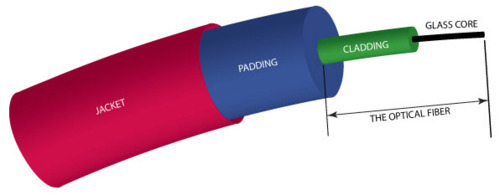
An optical fiber is a core glass fiber sheathed in a cladding of a different type of glass. This fiber is what carries the signal. Protecting this is a padding material of some sort to cushion the inner core. The cable is then wrapped by a plastic jacket coloured to make it easy to identify the type of fiber.
At the ends of a cable is a connector. The typical connector types were outlined last week but all of them have a ceramic piece embedding the end of the cable known as a ferrule. This is usually the piece that inserts into a socket and makes physical contacts with another fiber or a transceiver. With high quality connectors, the air gap is minimized and the insertion loss would typically be lower than 0.2dB (lower is better).
Signal Losses
Since they’re immune to electromagnetic interference, the primary concern for optical fiber is how much the signal drops when it goes through a cable and the connections on each end. Attenuation is the loss of signal strength from travelling through the fiber itself. Because of high quality glass, attenuation is typically low for modern optical fiber; the higher the glass quality, the lower the attenuation.
Other significant sources of signal loss are return and insertion losses. Return loss occurs at the end of an optical fiber cable where light being carried by the fiber is partly reflected back where the glass fiber meets air. This reduces the signal strength leaving the fiber and can even cause interference with the incoming signal. This effect can be addressed with the way the end of the optical fiber is shaped but there’s a small trade-off in terms of insertion loss.
Insertion loss also occurs at the end of an optical fiber cable but more accurately, it takes place in the air gap junctions whether it is between two fiber cables or a fiber cable and a transceiver. Because light isn’t carried along with the total internal reflection effect of a fiber in the air gap, light can escape and reduce the signal. With an appropriate well-built connector, this type of loss can be minimized.
Polished, Angle Polished, and Ultra Polished Contacts
The standard connector end of an optical fiber cable holds the ceramic ferrule in which the fiber is embedded. The piece has a polished face which will contact the receptor (whether another cable or a transceiver). This is good for standard configuration but there are higher quality contacts designed for more stringent conditions. These are the Angle and Ultra Polished Contracts.
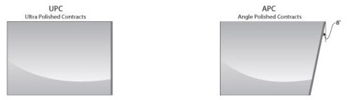
The difference between an Angle Polished Contact and an Ultra Polished Contact is the angle at which the flat face at the end of an optical fiber is polished to. UPC has this face square to the fiber while APC sets the angle at 8 degrees. These two types have their own advantages and as usual there’s a trade-off that needs to be considered.
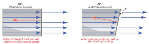
The advantage of UPC is that the insertion loss is very low and there’s no need to worry about the connection rotating since the fiber is symmetrical around the core. However, the flat face of UPC reflects light straight back down the cable and thus doesn’t help against return losses. The modification of APC’s 8 degree polish angle helps mitigate return losses. Light isn’t reflected straight back but at an angle into the cladding where it dissipates. However, the angled face makes it more difficult to ensure there’s no air gap between connections while rotation can also increase the size of the gap. With high quality construction, this gap and rotation can be minimized to the point where the insertion loss is only marginally greater than with UPC. In terms of numbers, the return loss for APC would be around 65dB while UPC return losses are around 55dB (higher is better).
Because return losses are larger than insertion losses, while the insertion loss difference between APC and UPC is small because of tight manufacturing, APC is overall better for reducing losses. Both of these improved connectors over the standard PC are available for special order here at Lin Haw.
Superior Quality Glass
The optical fiber cables at Lin Haw all use high quality Corning glass which provides two advantages: durability and lower attenuation. Signal attenuation losses are directly related to the glass quality so better glass means less signal loss over a distance. The glass is also more durable so even though Lin Haw’s optical fiber is still fragile (as any length of glass with the thickness of a human hair would be), it’s still surprisingly tough and can endure some shocks without breaking.
Jacket Fire Ratings
When cabling is pulled through an area of a building used for air flow or distribution, the cable jackets must be made to avoid giving off toxic fumes if there was a fire. These are Optical Fiber Nonconductive Plenum (OFNP) cables and they are available for special order. For regular risers, this level of fire safety isn’t necessary and there’s a different type of jacket available. Our normal inventory consists of these Optical Fiber Nonconductive Riser cables.
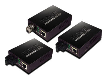
Media Convertors
When there’s a need for an optical fiber network to connect to an Ethernet network, devices will be needed to interface between the two. A media convertor can be plugged into an Ethernet switch and change the signal into the optical fiber equivalent. The function is two-way so at the other end another media convertor is used to change back to Ethernet.
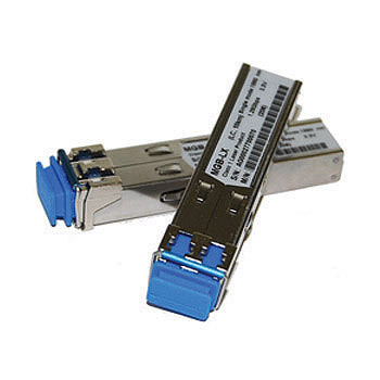
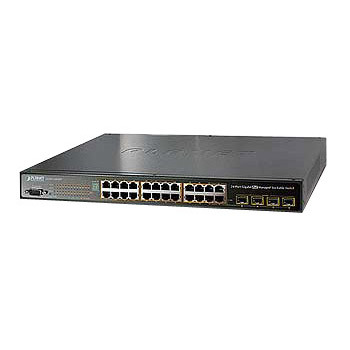
A similar device can also be used with some switches to connect them together. These are Gigabit Interface Convertors (GBIC) which are hot-swappable devices that slot into supporting switches. This allows connecting Ethernet switches together with the benefits of optical fiber. GBICs are specific to the switch vendor so Planet brand switches will only work with Planet GBICs.
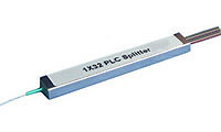
Planar Lightwave Circuit Splitters (PLC Splitter)
We’ll end off with a quick highlight on Planar Light Wave Circuit Splitters. These devices operate entirely passively, using no power, and allow multiple optical fiber systems to connect to a single main interface. On one end is a single fiber connected to the network interface while the other end features multiple fibers that are connect to various systems. These devices are important for Fiber to the Home (FTTH) implementations to share out the main connection. Multiple home units can thus be served by optical fiber. PLC splitters are available in different split numbers (from 1:4 to 1:32 or 2:4 to 2:32) and can even be cascaded if necessary, albeit with greater attenuation.
Conclusion
Optical fiber is available and useful for many purposes, particular when long range is required. Lin Haw has a large selection of optical fiber available ranging from inventory patch cords to special order cables with specialized connectors and fire-safe jackets. While there are places copper-based Ethernet is more suitable, optical fiber plays its own role in the places Ethernet isn’t as suitable.
Fiber Optics 101 (part 2):